A decoder is a circuit that changes a code into a set of signals. It is called a decoder because it does the reverse of encoding, but we will begin our study of encoders and decoders with decoders because they are simpler to design.
A common type of decoder is the line decoder which takes an n-digit binary number and decodes it into 2n data lines. The simplest is the 1-to-2 line decoder. The truth table is
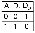
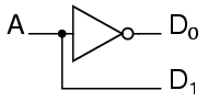
A is the address and D is the dataline. D0 is NOT A and D1 is A. The circuit looks like
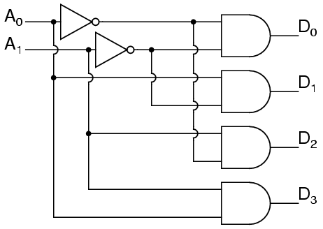
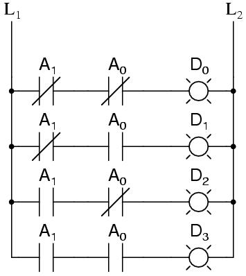
Only slightly more complex is the 2-to-4 line decoder. The truth table is
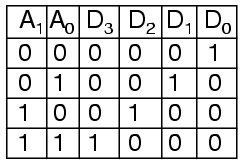
Developed into a circuit it looks like
Larger line decoders can be designed in a similar fashion, but just like with the binary adder there is a way to make larger decoders by combining smaller decoders. An alternate circuit for the 2-to-4 line decoder is
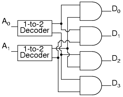
Replacing the 1-to-2 Decoders with their circuits will show that both circuits are equivalent. In a similar fashion a 3-to-8 line decoder can be made from a 1-to-2 line decoder and a 2-to-4 line decoder, and a 4-to-16 line decoder can be made from two 2-to-4 line decoders.
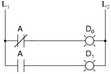
You might also consider making a 2-to-4 decoder ladder from 1-to-2 decoder ladders. If you do it might look something like this:
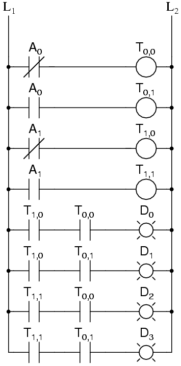
For some logic it may be required to build up logic like this. For an eight-bit adder we only know how to sum eight bits by summing one bit at a time. Usually it is easier to design ladder logic from boolean equations or truth tables rather than design logic gates and then "translate" that into ladder logic.
A typical application of a line decoder circuit is to select among multiple devices. A circuit needing to select among sixteen devices could have sixteen control lines to select which device should "listen". With a decoder only four control lines are needed.
[http://www.malayalam.net/howto/LessonsInElectricCircuits/Digital/DIGI_9.html]

